


























Test your RV battery disconnect and find parasitic loads before storage
Test an RV battery disconnect safely with a DC clamp meter, isolate owner-accessible parasitic loads, estimate storage loss, and apply the correct battery-manufacturer instructions.


By Romana | September 13, 2026
A battery disconnect should make storage simple: switch it off, verify that current leaving the battery falls to the meter's zero range, and deal with anything still drawing power. The catch is that an RV may have more than one battery bank, more than one disconnect, and loads wired around the coach switch. A light going dark proves only that one light lost power.
This guide uses a DC clamp meter because it can measure without opening the battery circuit. It is a screening and isolation procedure, not a wiring repair. The manuals for the exact RV, battery, inverter/charger, converter, solar controller and meter control the work. If those documents conflict with this guide, follow the documents.
Know when this is not a DIY test
Stop before measuring if the battery is swollen, cracked, leaking, unusually hot, hissing, smoking, giving off a strong odor, or surrounded by melted or charred wiring. Keep sparks and flames away, leave the area if conditions are worsening, and contact emergency services when there is an active fire or immediate danger.
Call an RV electrical technician instead of proceeding when:
- you cannot identify the house and chassis banks or their disconnects;
- the battery compartment requires working under the RV or removing a heavy battery;
- exposed conductors cannot be accessed without opening a 120-volt panel, inverter, converter or battery enclosure not intended for owner service;
- the system is 24 or 48 volts, uses a high-voltage traction pack, or has unfamiliar series/parallel wiring;
- cable insulation, lugs, fuses or busbars show heat damage or corrosion;
- a breaker or fuse opens again after replacement;
- current is large, unstable, or beyond the meter's range;
- the battery-management system reports a fault; or
- the result makes no sense after the checks below.
Winnebago's 2026 Solis manual, for example, tells owners not to remove its under-coach house batteries and to use a dealer or service center. It also calls for jewelry removal, protective clothing and eye protection around batteries.[2] That limit is specific to the Solis, but the lesson travels well: access can turn a simple measurement into a shop job.
What the disconnect test can prove
The test answers three separate questions:
- Does the named disconnect materially reduce current from the bank?
- Does any measurable current remain after the switch is off and electronics have gone to sleep?
- Which owner-accessible branch accounts for that current?
It does not certify the wiring, prove battery capacity, or tell you that every safety device is powered. It also does not test the chassis battery unless you measure that bank separately.
A clamp reading is only as good as the conductor you choose. Clamp around one main battery cable that carries all current into and out of the bank. If parallel paths bypass that cable, the meter will miss them. A permanently installed battery shunt has the same boundary problem when equipment is connected on the battery side of the shunt.
Tools and setup
Use the RV and component manuals, a circuit directory, a notepad, eye protection, insulated hand tools where the manuals require them, and a DC-capable clamp meter with enough low-current resolution for the expected draw. An AC-only clamp cannot measure a steady 12-volt DC load.
Fluke's clamp procedure says to disconnect probe leads, keep fingers behind the meter's tactile barrier, select DC current, let the display settle, and zero the clamp with closed jaws and no conductor inside. It then calls for one conductor centered in the closed jaw.[1] Follow your meter's manual because buttons, ranges, accuracy and safe working limits differ.
Do not improvise an in-series ammeter test at the battery. A handheld multimeter in its current mode becomes part of the circuit. An unexpected inverter start, pump, slide, jack, heater or charging source can exceed the meter input and create a dangerous fault. If your clamp cannot resolve the remaining current, use a correctly installed shunt or have a technician perform the low-current test with properly rated equipment.
Safe measurement workflow
1. Document the system before touching switches
Photograph the battery label, cable layout and switch positions. Record battery chemistry, bank voltage, number of batteries, and whether the coach has solar, an inverter/charger, generator auto-start, a battery combiner or a separate chassis disconnect. Find the manufacturer's storage procedure now, not after the battery is isolated.
2. Remove charging sources and commanded loads
Park in a dry, ventilated location. Set the parking brake. Turn off the generator and auto-start. Unplug shore power. Shut down the inverter by its manual rather than assuming the coach switch controls it. Disable or cover solar only by the solar-controller and RV manuals; live photovoltaic wiring is not an owner experiment. Stop the engine and remove charging sources that can distort the reading.
Turn off lights, fans, water pump, furnace, refrigerator, tank heaters, entertainment equipment, USB outlets and aftermarket gear. Close doors or latch switches so courtesy lights are off. Do not operate slides, jacks, awnings, starters or other high-current loads while a measurement is in progress.
Winnebago warns that all 12-volt equipment must be off and shore power disconnected before battery cables are removed.[2] This workflow does not require cable removal, but the same shutdown discipline prevents a load from waking unexpectedly.
3. Inspect, then take an ON baseline
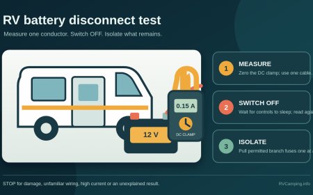
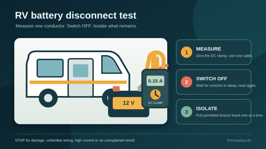
Do not disturb a damaged connection. If the compartment looks sound and the manual permits access, zero the DC clamp away from the cable, then place it around a single main battery conductor. Note current direction and record the reading with the disconnect ON. Wait for timed lights and control modules to settle.
The number may move as electronics sleep or cycle. Record a stable range and the elapsed time rather than chasing the last digit. If the current exceeds the clamp's range, remove the clamp and stop. Do not try a smaller range until the meter manual says it is safe.
4. Switch the coach disconnect OFF
Keep the clamp in the same place. Move only the intended disconnect, then wait the same settling period. Record the OFF reading and test a few low-risk cabin controls, such as a ceiling light, without energizing a motor load.
Interpret the result this way:
- If the current falls to zero within the meter's stated resolution and expected uncertainty, the switch isolated everything that passes through that measured cable at that moment.
- If current drops but remains measurable, the switch removed some loads while at least one path remains.
- If current barely changes, you may have the wrong switch, the wrong bank, a failed switch, a bypassed circuit, a charging source, or a conductor that does not carry the whole bank.
- If the sign reverses or the value wanders, check for solar, converter, alternator, battery combiner or generator activity before blaming a load.
Do not declare a universal "acceptable" parasitic current. Some safety or control circuits are intentionally live, and the battery maker's storage limits matter more than an arbitrary milliamp target.
5. Translate a steady draw into storage loss
Use the stable amperage only as a planning estimate:
amp-hours per day = amps × 24
A steady 0.15-amp draw uses about 3.6 amp-hours per day, or 50.4 amp-hours in 14 days. Even 0.03 amp amounts to about 21.6 amp-hours over 30 days. Real results vary with temperature, cycling loads, battery age, self-discharge and the point where a BMS or low-voltage device opens the circuit.
That arithmetic tells you whether the finding matters on your storage schedule. It does not tell you how much capacity is safe to use. Apply the limits in the exact battery manual.
Find the branch without turning the fuse panel into a guessing game
If the OFF reading remains measurable, compare the wiring diagram and fuse directory with what stays alive. Common candidates include propane or carbon-monoxide alarms, radio memory, leveling or slide controls, inverter standby, solar and battery monitors, cellular equipment, entry steps, hydraulic controllers, aftermarket trackers and equipment wired directly to a battery or busbar.
A 2026 Solis provides a useful model-specific example. Its propane detector always draws a small amount of house-battery current, yet the detector loses power when the coach disconnect or battery cable removes power. Its converter charges the house battery from shore power only when the disconnect is ON.[2] Other RVs use different boundaries. Never infer your alarm or charging state from the switch label alone.
Use this isolation order:
- Leave shore power, generator, engine and inverter off.
- Keep the disconnect in the position that produced the unexplained reading.
- Wait for a stable reading and photograph the fuse panel directory.
- If the RV manual permits owner fuse removal, pull one clearly identified 12-volt branch fuse at a time with the proper fuse tool.
- Wait for the same settling interval, record the change, and reinstall the same fuse in the same position before moving on.
- Stop when the reading changes sharply; identify every device on that branch from the diagram and labels.
Never substitute a larger fuse. Do not pull chassis, airbag, engine-control, battery-main, inverter, slide, jack or unlabeled high-current protection as a diagnostic shortcut. Do not open a 120-volt panel. A branch that contains a safety alarm may be identified for documentation, but it should not be disabled while anyone occupies the RV. If no owner-accessible branch changes the reading, suspect a direct-to-battery or battery-side connection and hand the circuit map to a technician.
The storage decision depends on battery chemistry
Flooded and AGM lead-acid
Trojan says the lead-acid products covered by its guidance should be completely charged before storage, kept cool and dry, monitored by voltage or specific gravity as applicable, and boosted at 70% state of charge or below.[3] It also notes that heat speeds self-discharge. Do not copy Trojan's threshold to another brand without checking that battery's manual.
For a lead-acid bank, choose between complete isolation and a manufacturer-approved maintenance charge. The RV, charger and battery instructions must all agree. A charger that lacks the proper storage profile can overcharge, while an isolated battery still self-discharges. Flooded batteries also have electrolyte and ventilation requirements that do not apply to sealed AGM batteries.
LiFePO4 is not one storage recipe
Two current manufacturer instructions show why "charge lithium to X percent" is bad universal advice. Battle Born's May 2026 off-season guide tells owners of its batteries to start fully charged and disconnect every load and charging source, including the inverter, monitor and small parasitic loads.[4] Renogy's manual for one 12.8-volt 300Ah Core model instead specifies 30% to 50% state of charge, disconnection from the system, and recharge every three to six months.[5]
Neither instruction controls a different battery. Follow the exact brand, model and revision for storage state of charge, temperature, BMS sleep or power-off procedure, heater wiring, inspection interval and allowed charging temperature. A BMS shutdown is protection, not a storage plan. Renogy warns that severe over-discharge from self-discharge or parasitic loads requires the battery to be taken out of use until the fault is corrected and it can be charged.[5]
Chassis and house banks are separate jobs
A coach switch may leave the starting battery untouched. Test the chassis bank only through its vehicle manual and with equipment suitable for automotive standby current. Modern vehicles wake modules when a door opens, a key approaches or a network message arrives, so a quick reading can be misleading. Do not pull vehicle fuses or interrupt security, airbag or engine-control circuits unless the chassis service procedure calls for it.
Before you leave the RV
Record the ON and OFF readings, clamp model and range, settling time, measured cable, charging-source state, fuse changes, battery state of charge, storage switch positions and next inspection date. Restore every diagnostic fuse and protective cover. Put the meter leads back in the voltage/ohms jacks if its manual calls for that, so the next user does not accidentally probe voltage with the lead in a current jack.
Confirm what happens to smoke, propane and carbon-monoxide protection when the bank is isolated. An unpowered propane detector does not protect an occupied RV. Follow the RV's storage procedure for propane and occupancy, then test every alarm according to its manual when power is restored.
A useful outcome is not merely "the switch works." It is a written boundary: which bank the switch controls, what remains connected, how quickly that remainder consumes capacity, and what the battery manufacturer requires until the next trip. If any part of that boundary remains unknown, schedule a technician before storage rather than letting the battery become the test instrument.
Source note: This original RVCamping.info guide combines measurement instructions from a test-equipment manufacturer with current RV and battery-manufacturer documents. Product-specific examples illustrate why switch boundaries and storage settings vary; they are not universal specifications.
Sources
- How to Measure Current with a Clamp Meter (accessed September 13, 2026)
- 2026 Winnebago Solis Operator Manual (accessed September 13, 2026)
- Trojan Battery Maintenance (accessed September 13, 2026)
- How to Store LiFePO4 Batteries During the Off-Season for RVers (accessed September 13, 2026)
- Renogy Core Series 12.8V 300Ah LiFePO4 Battery User Manual (accessed September 13, 2026)
What's Your Reaction?