







Your RV has more than one charger: audit every path before cold weather
Map shore, solar, alternator/DC-to-DC, and generator charging paths against the exact lithium battery temperature, current, and BMS limits.

Your RV has more than one charger: audit every path before cold weather
By Romana | October 17, 2026
An RV lithium battery does not care whether charging current began at a campground pedestal, a solar panel, the engine alternator, or a generator. It only sees what arrives at its terminals. That is why checking one “lithium” setting is not a cold-weather charging plan.
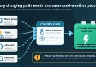
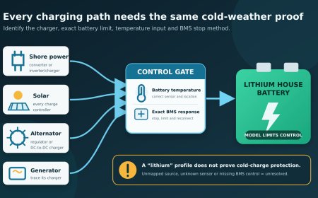
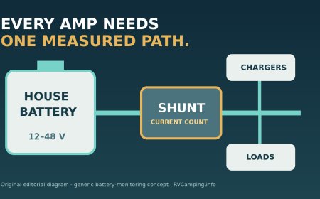
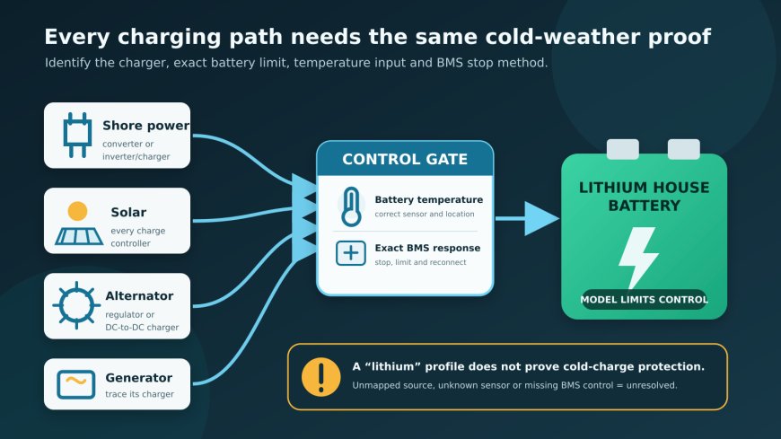
A typical RV can have several ways to charge the house bank. Shore power may feed a converter or an inverter/charger. Solar has its own controller. A motorhome or tow vehicle may supply current through an isolator, regulator, or DC-to-DC charger. A generator often energizes the same AC charger used on shore power, though some installations have another route. Any path that can put current into the bank belongs on the audit.
The temperature limit is also not a universal LiFePO4 number. The current Victron Lithium NG 12.8V manual allows charging only from 5°C to 50°C (41°F to 122°F), limits charge current below 15°C (59°F) to 0.3C, and says its BMS turns chargers off below 5°C.[1] RELiON's general LiFePO4 instructions describe a different envelope: reduced charging at 0°C to -10°C (32°F to 14°F) at 0.1C, then -10°C to -20°C (14°F to -4°F) at 0.05C.[2] Those values are examples of why the exact battery model, data sheet, BMS, and charger manuals must control the decision.
Start with the battery, not the weather app
Outside air temperature is useful context, but it is not necessarily battery temperature. A bank may sit in a heated interior compartment, an exterior box, a basement near ductwork, or a metal enclosure that lags behind a quick warm-up. The relevant number is the temperature measured where the battery manufacturer says it should be measured.
Build a battery identity record before changing any setting:
- manufacturer and exact model or part number;
- nominal voltage, capacity, chemistry, and number of batteries;
- series or parallel arrangement;
- BMS model, whether internal or external;
- heating equipment, if fitted, and how it is controlled;
- model-specific allowable charge-temperature range;
- reduced-current zones, maximum current, charge voltages, and reconnect conditions;
- the manual or data-sheet revision used for every value.
Do not borrow a threshold from another brand, an older product line, or a forum post. Even two LiFePO4 manuals can give materially different cold-charge instructions. Victron's current Lithium NG manual requires an approved NG BMS, monitors battery temperature, and defines a low-temperature alarm that turns charging off.[1] RELiON tells readers to consult the specific battery data sheet for BMS cutoff and reconnect values, even though its charging document gives general temperature bands.[2]
Write the actual limit in the audit sheet, not “has cold protection.” Protection can mean a BMS blocks charge, a charger reduces current, or some coordinated combination of battery and charger controls.[1][3] Those are different behaviors.
Draw every charging path
Start at the battery positive bus or terminal and work outward on paper. The aim is identification, not disassembly. Use labels, owner documents, build sheets, control screens, and photographs that can be obtained without opening energized equipment or reaching into unsafe spaces.
A useful path map has one row for each source:
| Charging opportunity | Equipment to identify | What the audit must prove |
|---|---|---|
| Shore pedestal | Converter or inverter/charger | Exact charge profile, current limit, and BMS-controlled shutdown |
| Roof or portable solar | Every solar charge controller | Correct battery profile and a reliable stop or current limit at the battery's temperature boundary |
| Engine running | Alternator path, isolator, regulator, DC-to-DC charger | Alternator protection, current limiting, and BMS response |
| Generator | The AC charger it supplies, plus any separate DC output actually connected | Same proof as shore charging, without assuming the shore and generator paths are identical |
| Service or portable charger | Charger model and connection point | Model-specific compatibility and supervised use allowed by the battery maker |
One physical box can perform several functions, and one source can pass through more than one box. A combined inverter/charger may handle shore and generator charging. A power center may contain a converter that is separate from the inverter. The map should follow the current path rather than relying on panel labels.
Victron's Lithium NG manual treats AC chargers, inverter/chargers, solar chargers, and DC-to-DC chargers as charge sources that need the correct LiFePO4 profile or adjustable parameters.[1] Its Lynx Smart BMS NG documentation says all loads and chargers must be controllable through its supported digital control or allow-to-charge/allow-to-discharge signals for the system to operate correctly.[3] That system-specific requirement illustrates the audit question: can the installed BMS stop every charger that exists?
Audit shore power and the generator together, then separately
Plugging into shore power usually creates AC power first; a converter or inverter/charger then turns it into DC charging current. A built-in generator commonly supplies that same AC system. If both sources feed the same charger, they may share its profile and temperature response.
“Commonly” is not proof for a particular RV. Confirm the actual equipment and transfer path. A generator may have a separate charging output, an aftermarket charger may have been added, or a control mode may differ when the generator runs. Record the charger model that becomes active on shore power and the charger model that becomes active on generator power. If they are the same unit, say so. If the documentation cannot settle it, have a qualified RV electrical technician trace and test the system.
For each AC-powered charger, capture:
- exact maker, model, firmware, and manual revision;
- selected battery profile and its voltage/current values;
- temperature sensing location, if the charger uses one;
- the method by which the BMS tells it to stop charging;
- what the charger displays or logs when charging is blocked;
- whether it resumes automatically, and the documented reconnect condition.
Do not test a low-temperature cutoff by intentionally chilling a battery and forcing current into it. Review the design and manufacturer-approved commissioning records instead. Victron's commissioning checklist calls for verifying that its BMS turns off all charge sources when a BMS cable is disconnected, but that is a procedure for the named Victron system and qualified installation context, not a generic RV test.[1]
Solar is the path most likely to be forgotten
Solar can begin producing current as soon as daylight reaches the panels. That may happen before the furnace warms the battery compartment, while the RV is in storage, or while nobody is watching the control panel.
Inventory every controller, including a separate portable-panel controller. Record its battery profile, maximum output, temperature behavior, remote on/off capability, and connection point. Then document how the battery or BMS prevents that controller from charging outside the battery's allowed range.
A setting labeled “lithium” is not enough. For the 12.8V Lithium NG line, Victron specifies 14.2V absorption, two hours of absorption, 13.5V float, and no voltage temperature compensation; it separately limits the temperature range and cold-weather current.[1] RELiON's general document lists ranges rather than those same fixed values and directs owners to the specific battery data sheet.[2] Profile names do not prove that the numbers match.
The alternator path has two things to protect
Lithium batteries can accept high current, so alternator charging must respect the house battery and the charging source. Victron warns that low internal resistance can pull high charging current and calls for alternator capacity, temperature regulation, and current limiting such as a DC-to-DC charger or converter.[1] RELiON likewise warns that poor alternator regulation can lead to a BMS disconnect and possible alternator damage; it identifies a compatible regulated alternator or DC-to-DC charger as the controlled approach.[2]
The audit should identify the alternator, any second alternator, isolator or combiner, external regulator, DC-to-DC charger, ignition trigger, and BMS control connection. Then compare the charger's maximum current with the battery's normal and cold-temperature limits.
C-rate needs arithmetic. For a 100Ah battery, 0.3C is 30A and 0.1C is 10A under the respective manufacturers' stated C-rate limits.[1][2] With more than one battery, use the bank configuration and the manufacturer's rule for how current is shared. Do not assume that a charger rated at 50A always sends 50A, or that a 50A label is acceptable in every temperature band. Put the permitted amperage beside the installed charger's configured limit.
Avoid bypassing an isolator, contactor, ignition lead, or BMS signal to make a charger wake up. That can remove the very control intended to stop cold charging or protect the alternator. Wiring changes and commissioning belong to a qualified installer working from the manuals for the exact equipment.
Treat the BMS as a control system, not a permission slip
A BMS cutoff is a last protective boundary, not evidence that every upstream charger is configured correctly. The audit must answer four separate questions:
- What temperature does the battery or BMS actually measure?
- At what exact value does it reduce or prohibit charge for this model?
- How does that instruction reach each charger?
- What happens at cutoff and reconnect?
In Victron's Lithium NG system, the battery reports temperature to the BMS, and the BMS can stop chargers through charge-disconnect signaling or supported digital control.[1] The Lynx Smart BMS NG manual says its allow-to-charge contact opens when temperature is too low and emphasizes that all chargers must be controllable by the BMS-supported methods.[3] This is a coordinated architecture. It should not be generalized to a drop-in battery with an internal BMS and unrelated chargers.
If a battery has an internal low-temperature cutoff, find the exact cutoff, reconnect temperature, sensing method, and behavior after disconnect in that model's documentation. If it is sold as heated, record the documented heater supply and charging sequence. Do not infer either one from a “heated” label.
A practical cold-weather audit sheet
Finish with one table that can live in the RV manual folder:
| Path | Source and charger model | Max configured current | Battery limit at present temperature | Temperature source | BMS stop method | Result |
|---|---|---|---|---|---|---|
| Shore | Pass / unresolved | |||||
| Solar 1 | Pass / unresolved | |||||
| Solar 2 or portable | Pass / unresolved | |||||
| Alternator/DC-to-DC | Pass / unresolved | |||||
| Generator | Pass / unresolved | |||||
| Portable/service charger | Pass / unresolved |
Mark a path “pass” only when its identity, settings, temperature input, and BMS shutdown method match the exact battery requirements. “The BMS should catch it” is unresolved. So is a charger hidden behind a panel with no readable model number.
Until every active path is accounted for, prevent unattended charging in cold conditions using only the shutdown or storage method approved in the installed equipment manuals. Do not improvise by pulling unidentified conductors, defeating interlocks, or changing protection settings. A qualified RV electrical or battery-system technician should resolve missing labels, undocumented modifications, incompatible equipment, or any system that cannot demonstrate BMS control over all chargers.
The useful result is not a generic winter setting. It is a map showing which device can charge the bank, the exact temperature and current limits for that battery, and the documented control that stops each path before it crosses those limits.
Sources
What's Your Reaction?